|
 |
|
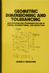
(per ASME Y14.5M- 1994)
James D. Meadows
624 pages, illustrated / $110.00
ISBN: 0- 8247- 9309- 9
This invaluable reference/text explains the symbology of
dimensioning and tolerancing and introduces a
step- by- step system for geometric definition
-
addressing functional requirements and manufacturing
techniques as well as measurement, inspection, and gaging procedures while illustrating
- with over 320
detailed drawings - how symbology is best utilized, in
what order symbology should be applied, and how each
geometric control anticipates, integrates, and
complements all other geometric controls on a part in an
assembly.
Now in it's 11th printing (since May 1995 release) -
thousands of copies purchased! |
|
|
|
Demonstrating practical techniques that promote communication
and cooperation between job disciplines, Geometric Dimensioning and
Tolerancing:
- Shows how to save time and money by avoiding potential
problems in functionality, part manufacture, and measurement
- Explains international standards and technical reports
- Helps improve manufacturing techniques and quality by
discussing methods of collecting variable and attribute
inspection data on products
- Provides design tools that increase tolerances without
adversely affecting functionality
- Delineates concurrent engineering procedures and clarifies
practical, easily accessible tolerancing
techniques
- Furnishes the latest rule changes in the American national
standard on dimensioning and tolerancing, dimensioning and
tolerancing mathematics, and measurement methods
...and much more!
Written by an acknowledged expert in the
field and certified ASME Y14.5.2 Senior Level Geometric
Dimensioning and Tolerancing Professional, Geometric Dimensioning
and Tolerancing is an indispensable reference for mechanical,
manufacturing, design, quality control, project and process
engineers and managers, metrologists, and draftspersons, and an
incomparable text for continuing technical education, undergraduate,
and graduate students in these disciplines.
[Text Contents]
Introduction
- Geometric Product Definition Principles
- Verification of Position
- Geometric Characteristic Symbols
- Chart of Symbols
- Rules Sheet
Chapter #1 Geometric Dimensioning and Tolerancing
- An Explanation of Tolerance Zone Conversions
- Surfaces, Features, Features of Size, Datum Features, Datum
Features of Size, and Datums
- Tolerances
- Components Common to a Geometrically Dimensioned and Toleranced
Drawing
- Fits and Allowances
Chapter #2 Maximum Material Condition, Least Material Condition, and
Regardless of Feature Size
- Maximum Material Condition: Meaning and Uses
- Least Material Condition: Meaning and Uses
- Regardless of Feature Size
Chapter #3 How to Read a Feature Control Frame
Chapter #4 Size Controls Form
- The Taylor Principle
- Gaging Size Limits
- Merging Theory with Reality
Chapter #5 Rules, Concepts, Characteristics, and Untoleranced
Dimensions
- Individual or Related to Datums
- Material Conditions
- Untoleranced Dimensions
- Components Common to a Feature Control Frame
Chapter #6 Datums
- Datum Features
Concurrent Engineering
Two Coaxial Diameters as a Datum Feature
Pattern Datums
Datum Features of Size at MMC
Threads, Gears and Splines
Datum Targets
- Oddly Configured and Curved Surfaces as Datum Features
- Equalizing Datums
- Datum Feature Symbols
- Flexible Parts
Position and Profile Using Compound Datums (Two Holes)
Common Misconceptions
New Revision ANSI/ASME Y14.5 - Change
Fixturing-Assuming Target Points are the Same as the Datum Planes
Two Mating Rigid Parts
Two Mating Flexible Parts
Free State Variation in Sheet Metal Parts
- Direct vs. Indirect Tolerancing
Chapter #7 The Maximum Material Condition Symbol and Its
Ramifications
Chapter #8 Relationships Between Individual Features
Chapter #9 Virtual Condition and Resultant Condition Boundaries
- Virtual Condition (MMC Concept)
- RFS Does Not Mean Tighter Fits
- Unique Effects on Controlled Features that Invoke the LMC Principle
- Wall Thickness Calculations
Chapter #10 Datum Feature of Size Representation
- Modes of Datum Feature Representation
- Angular Orientation
Chapter #11 Form Controls
- Flatness
- Straightness
A Versatile Form Control
Straightness of a Derived Median Line
Derived Median Plane Straightness
Straightness RFS
- Circularity
Theory vs. Reality
Circularity (Roundness) Measurement Instruments
- Free State Variation
- Cylindricity
Chapter #12 Orientation Controls
- Orientation Chacteristics
- Angularity
Angularity of a Feature of Size
Orientation of Line Elements
- Perpendicularity
Perpendicularity of a Cylindrical Feature of Size to a Datum Axis
- Parallelism
Chapter #13 Profile
- Line Element Controls
- The Power and Versatility of Profile to Control Irregular and
Unusual Features
- Composite Profile vs. Two Single- Segment Profile Controls
Chapter #14 Runout
- Circular Runout
- Total Runout
- Reactions to a Non- Perfect Datum Establishment
Chapter #15 Location
- Concentricity
- The Return of Symmetry
- Position
Floating Fasteners
Projected Tolerance Zones (Fixed Fasteners)
Inspecting Threaded Holes
Projected Tolerance Zones for Tight Fitting Holes
Comparison of Coaxiality Controls
Zero Tolerancing at MMC
Composite Tolerancing
Composite Positional Tolerancing - Tolerancing Mating Parts
Composite Positional Tolerancing vs. Two Single- Segment Positional
Tolerancing Controls
Converting from Plus and Minus to True Position Tolerancing
Chapter #16 A Logical Approach to Part Tolerancing
- Linear Segmented Thinking
- Refining Functional Geometric Controls to be More Cost Effective
- Implying a Manufacturing Sequence on Complex Part Configurations
- Centerplane Datums
Chapter #17 Dimensioning and Tolerancing Schemes
- Common Tolerancing Methods
- Design, Inspection, Production and Prototype Needs and Capabilities
regarding Dimensioning and Tolerancing Methods
Chapter #18 Steps for the Development of a Dimensional Inspection
Plan
- The Dimensional Inspection Plan Format
Plan Development
Each Measurement
What is being Verified?
Hard vs. Soft Gages
Choosing Gages
Determining Uncertainty
- A Dimensional Inspection Plan Example
Chapter #19 Graphical Data Analysis
- Graphical Inspection Data Analysis (Checking Datum- to- Pattern
Requirements)
- Composite Positional Controls (Checking Feature- to- Feature
Requirements)
- Pattern of Features Controlled to a Center Datum Feature of Size
- Analyzing Pattern/Datum Shift with Datum Features of Size
Referenced at MMC
- Visual Inspection of Positional Controls by Virtual Condition
Boundary Verification
Non- visual Techniques
Visual Techniques
Chapter #20 Functional Gaging
- Functional Gage Design
- Tolerance on the Work (Ten Percent of What?)
- Push Pin Gages (Advantages: Tolerance Distribution)
Considerations of Functional Gage Design, Dimensioning and
Tolerancing
Definitions
|
|
If you have any questions about
GD&T training, books, workbooks, tests or DVDs,
please reach out to James D. Meadows & Associates, Inc., at (615) 924-3600.
|


